Cleantechnica Article – Chemputer

This was published on cleantechnica.com months back. I did not realize it was not here until someone pointed it out…………

Recently a 3D printer called a “chemputer” was announced. The headline read: “Researchers developing ‘chemputer’ that prints drugs.” This device, if modified, has very serious potential for disruptive change.

With one of these modified chemputers, you have the ability to create any chemical compound you wish in less than a day. With several hundred of them, you have the ability to order a custom chemical, queue it for manufacture and later use. This is where things get interesting and science advances very quickly.

Imagine a researcher working on polymer (plastic) solar cells and having access to this technology. Before he had access to this technology, he was testing several samples a week. Now, his lab is upgraded to include a rack mount with one thousand chemputers, and a reel-to-reel unit for printing and testing polymer solar cells, after which the number of samples he can test skyrockets.

In a day, he can test several thousand possible cell designs. In a month, tens of thousands. And in a year, several hundred thousand. With evolutionary software helping with the design process, it would not be long before solar cells became extremely cheap and extremely efficient. The current yearly increases in efficiency and reduction in cost would become something that could happen weekly.

Now, lets go to the lab next door where the researcher is designing new batteries for energy storage…. :)

David Fuchs is a geek and builder of things. He’s a classically trained engineer and programmer involved in open source, software, and hardware. He’s interested in 3D printing and nanotechnology, predicting the future of technology, and low-cost power production in 3rd world nations using material at hand.

Originally published on Cleantechnica.com

http://cleantechnica.com/2012/09/09/chemputer/#l7qZRxYz7aWtgb38.99

Posted in Uncategorized | Leave a comment

Clean Technica Article – Graphene Silicon Nanoplatelets Increase Li-Ion Battery Capacity 4 Fold

Six months ago Northwestern University professor Harold Kung theorized that using a graphene silicon mixture, there was a way to extend a new lithium-ion battery’s charge by 10 times and increase its lifespan by a factor of 10. The technology theorized by Harold Kung could allow for cell phone batteries to be charged in 15 minutes and hold a weeks worth of charge. It could also allow greater range and faster recharging for electric vehicles. At the time he believed that silicon-graphene technology would be commercially viable in 3 to 5 years.

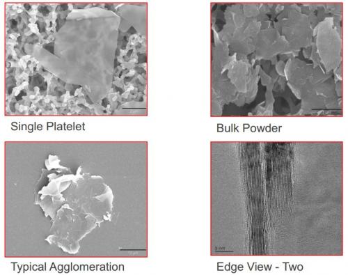
graphene nanoplatelets

I’ve got a surprise for you. XG Sciences has announced the immediate availability of a graphene silicon additive for lithium-ion batteries in commercial scale quantities. These graphene nanoplatelets will allow lithium ion batteries to hold four times the amount of energy and extend the lifespan of the batteries substantially. This technology holds great potential for extending the range of electric vehicles, increasing the time between charges for portable consumer electronic devices, decrease the weight of portable electronic devices, and decreases the cost for the storage of electrical energy from solar cells for nighttime usage.

David Fuchs is a classically trained engineer and programmer. He is involved in open sourcing, software, and hardware. Current interests: 3d printing and nanotechnology, predicting the future of technology, and low-cost power production in developing nations using material at hand. You can check out his website for more of his writing, and you can contact David on Google + 


Published originally on
http://cleantechnica.com/2013/04/22/graphene-silicon-nanoplatelets-increase-lithium-ion-battery-capacity-4-fold/

Posted in Uncategorized | 7 Comments

Just Some Thermo Geek Stuff

Tonight I was asked a question in IM (instant messenger) that I thought was interesting. It ran along the lines of … and this is paraphrased …

“If you had a shipping container full of dirt, how much more energy will it have when it is 20 degrees hotter?”  I am assuming it was 20 degrees Celsius due to the EU origin of the question.

In a 20 foot by 9 by 9 foot shipping container you have about 33 cubic meters.

Lets use sand since it is cheap and easier to store and deal with than water. Sand has roughly half the heat storage capacity of water.

Heat stored in 33 m3 sand heated 20 C can be calculated as

q   = (33 m3) (1800 kg/m3) (835 J/kgC) ((90 C) – (70 C))
= 991,980 kJ
= (991,980 kJ)/(3600 s/h)
= 275.55 KwH

So for a 20 degree C rise in temperature, in 33 cubic meters of sand, you have stored a quarter of a megawatt hour of energy. To bring that into perspective, that is a 255 hp gasoline powered car, on a track, all out for a full hour, or a mid sized house for a week. All stored in a shipping container full of dirt.

Not a shipping container

Reference material

http://www.engineeringtoolbox.com/sensible-heat-storage-d_1217.html
http://en.wikipedia.org/wiki/Heat_capacity

<- Previous   Next ->                               Contact

Posted in Uncategorized | Leave a comment

Honeycomb Solar Thermal Panel

In the late 80’s at school we took two layers of bubble wrap and put it beneath the glass sheet in a solar thermal panel. It improved winter efficiency of the panels quite a bit. However, the bubble wrap melted as soon as the temperature went up, as spring began.

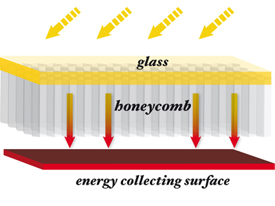
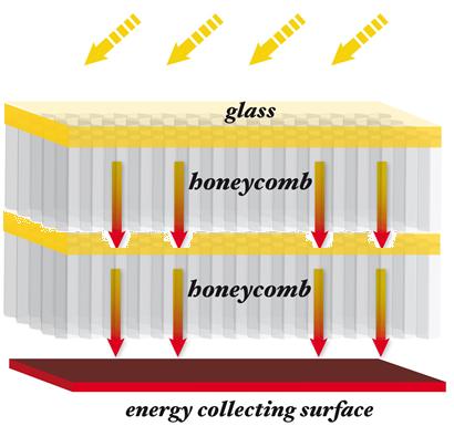
The two layers of bubble wrap were replaced by a checker board pattern of very thin, 1 inch tall plexiglass, overlapped in a ~1/2 inch square pattern. This was later doubled up, glass, honeycomb, glass, honeycomb, heat sink, this increased efficiency. The outer layers of glass and honeycomb were nothing more than dead air space used as insulation.

A company called TIGI recently reinvented the wheel. The panels they created look like this.

Our first iteration along the same lines looked almost identical to the image above.  The second iteration was as shown in the following image.

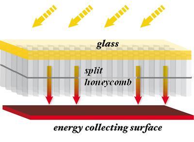
With an extra layer of tempered glass the costs were to high for production. So the following design was created but never produced. The honeycombs were to be split down the middle, the upper and lower portions are separated by a thin layer within the honeycomb. Much like the end cap on a honeycomb in a bee hive, only halfway down the honeycomb. This makes the upper section insulation, equivalent or better than a double pane window,  in the lower section heat is stored and transferred to the heat sink, improving performance.

<- Previous   Next ->                               Contact

Posted in Uncategorized | 3 Comments

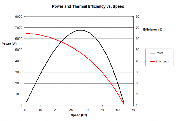
Stirling Power and Thermal Efficiency Curve


<- Previous   Next ->                               Contact


Posted in Energy | 3 Comments

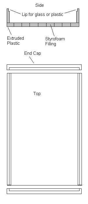
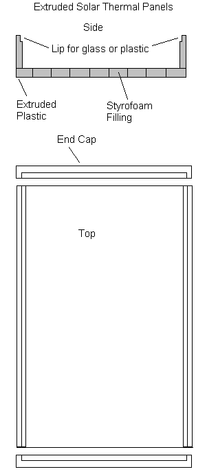
Extruded Plastic Solar Thermal Panel Case

It occurred to me that solar thermal panels could be produced for much less that the $150 USD per square meter that current panels cost. This can be done by extruding the case and filling it with insulation at the same time. This reduces the cost for the case to $15-$20 USD.

Using plastic instead of glass reduces the cost even further. The cost per 48 x 96 inch sheet is between $65 and $100 USD depending on thickness.

Aluminum tubing and coil runs from $1.5 to $2.0 per pound. Large rolls of aluminum coil are $1.50 to $2.00 per pound. The amount of aluminum used for both the heat collector and the piping is under 10 pounds.

Total cost for a 4 x 8 foot (3  m^2)  panel is approximately $100 to $140 USD. Making the cost per square meter $33 to $47 USD. Making these extruded panels cost less than 1/4 of the current commercially available panels.


 <- Previous   Next ->                               Contact

Posted in Thermal Solar Panels | 7 Comments

Cleantechnica Article – Using Thermodynamics and 100 Year Old Technology To Break The $20 per MWh Barrier

Possible Title : Using Thermodynamics and 100 Year Old Technology To Break The $20 per MWh Barrier 

Sub $20 per MWh Energy – Part 1 – Using Thermodynamics and 100 Year Old Technology To Break The $20 per MWh Barrier 

For years the production of energy has fascinated me. Over the past 20 years I have experimented with solar cells made via inkjet printer, a hydraulically coupled compressor and turbine based on Tesla’s turbine, vertical wind turbines, high temperature cracking of water, high COP heat pumps, all the different varieties of Stirling engines, and many other energy projects. Continuously going back to old projects to incrementally improve them and make them perfect has been fun, except perfect is the enemy of finished.

The week long power outage here in New Jersey, after hurricane Sandy, made me realize that we need simple, scalable, cheap, and locally produced power. Removing all distractions and giving an engineer of German lineage a week to think on a problem often gets the problem solved. After pulling out the 7 pocket expanding file with all my past Stirling designs, a couple note pads, my favorite gel pens, a dry erase board, and some reference books,  I began designing. As with any engineering project you need describe what you want to accomplish, and your limiting factors. Due to cost constraints, engineering is always compromise.

What is the goal?  An always on (24 x 7 x 365) power supply that is inexpensive to produce, can be bulk produced with readily available materials, can be manufactured in any nation using 1950’s or earlier technology, and has a working lifespan greater than 20 years.  (That sounds really simple doesn’t it?)

What are the design criteria?

  • Low Temperature Differential (LTD) Stirling based design.
  • All parts must be designed for high speed manufacture and assembly.
  • All materials used must be inexpensive and readily available.
  • The Stirling design must have the least number of wear points possible.
  • It must use inexpensive solar thermal panels for gathering energy.
  • The solar panels must be easily produced in an automated fashion.
  • It must have inexpensive (dirt cheap) energy storage.
  • It must produce 3 kW of power or more continuously (24 x 7 x 365 x 20).
  • On a daily basis, it must be capable of gathering two to three times the energy required for a 24 hour period, on the least sunny day of the year.  (NREL solar radiation manual)
  • It must be capable of storing the energy required for 3 to 5 days of continuous usage with no energy input.
  • Any person with basic mechanical skills should be able to install the system.
  • The total Levelized Cost of Energy (LCoE) must be under $20 per MWh.

The basic system layout.
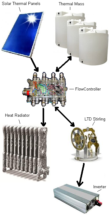
Semi-Steampunk Energy Flow Diagram

This system layout image represents the individual pieces and the energy flows between the individual components. The flow controller, controls the heat distribution between components.

The system consists of six main components. Solar thermal cells for gathering energy. An insulated thermal mass for storing the energy (dirt or water). A heat radiator for disposing of waste heat. An LTD Stirling engine for generating energy. A flow controller for for fluid flow, preventing energy loss from the system, and increasing efficiency. An inverter to connect to the grid and convert DC power from the generator to AC usable in your house and power grid.

Each component is designed to be as inexpensive, modular, easily replaceable, and mass producible  as possible.


Solar Thermal Panels absorb the suns energy in the form of heat. The price for solar thermal panels averages $150 per square meterExtrude plastic cased panels can reduce the cost to $33-$47 USD per square meter, with slightly lower efficiency.

Thermal Mass is a fancy engineering way of saying insulated pile of dirt or bucket of water. This is used to store the heat absorbed through the solar panels.  The cost of this varies greatly. It can be dirt insulated all around with hay bales and covered with plastic ~$600 USD,  4 – 2,500 gallon water tanks filled with water or sand ~$4,700 USD, a 9 x 20 shipping container insulated and filled with dirt or sand ~$1,100 USD, or an insulated hole in the ground ~$800 USD. This includes the cost of the aluminum tubing which runs from $1.5 to $2.0 per pound. There should be multiple thermal masses, or zones within a single thermal mass, each filled to thermal saturation in sequence.

Flow Controller is used to transfer liquid to and from each of the components. It is designed to keep as much heat in the system, and reuse the remaining heat as often as possible. When the system is energy saturated, or when there is no alternative, it will dump the energy out via the radiator. The multiple thermal masses or zones, at different temperatures, and external temperatures at different times of day, make waste heat reuse an efficient way to extract as much energy from the system as possible. This will run $150 to $300 USD.

Heat Radiator is used to radiate waste heat from the system, or as a heat sink when the system is saturated. This can be a standard aluminum fin radiator and fan, a cold body of water, a hole or trench in the ground with a pipe running into or through it, or any thing else at a lower temperature. The cost varies with type of radiator.

LTD Stirling is the key to this system. The design uses two separate heating and cooling chambers (upper and lower) with a shared piston, the volume is 9 cubic feet (68 gallons), it has 500 sq ft of radiator surface area (floor area of a large two car garage), it is 6.5 feet tall, 3.5 feet wide and 3 feet deep, can be vertically or rack mounted, and is designed to produce up to 6 kW of power, but will be run at 3-4 kW for greater efficiency. The larger these units are, the greater the radiant surface area. The slower they run the closer they can get to Carnot efficiencies. The full design specs are available here. These units can be daisy chained together, one to the next. The cost of this device is between $180 and $350 USD.

Grid Synchronized Inverter allows you to attach to the power grid. These are now commodity items and the price for a UL Listed 5 kW unit is from $1,000 to $2,500 depending on manufacturer.

System Cost is based on the location and available kWh/m^2/day (kilowatt hours per meter squared per day), on the least sunny month of the year, for me that is December. According to the NREL solar radiation manual for where I am, 50 miles south of New York City, that is 1.9 kWh/m^2/day. Over the period of a year the power varies greatly from 1.9 – 6.2  kWh/m^2/day.

3 kW continuous output, over a 24 hour period, with 30% efficiency, requires we gather 240 kWh, to produce the 72 kWh this system will produce over the period of a day. One of our design criteria is, we gather 2 – 3 times the power required for a given day. For safety the further north you go the higher the multiple should be. For where I am it is ~2.5, for Texas 1.9 – 2, for Maine 3.0.

Panel Cost
600 kWh = 2.5 x 240 kWh
315.78 square meter = 600 kWh \ 1.9 kWh/m^2/day
$10,428 = 315.78 sq meter * $33 per square meter

Other Costs
$1,100 – Thermal Mass (Shipping container or insulated hole in the ground)
$250 – Flow Controller
$200 – Heat Radiator
$250 – LTD Stirling
$1,500 – Grid Synchronized Inverter

$13,728 – Total Parts Cost

NOTE: None of these calculations take into account the reuse and recycling of the energy gathered, by cycling the energy into other zones or thermal masses at lower temperatures. (IE 90 C –> 60 C –> 30 C –> radiator, where “–>” is the LTD Stirling, and the temperatures are of different zones or thermal masses) Above are worst case calculations.  

The thermodynamic efficiency of a solar based  LTD Stirling changes based on time of year, and time of day, based on the outside (radiator) temperature. It is not that Carnot takes a holiday (eff not = 1 – tc/th). It is that the temperature differential changes, changing the efficiency. The greater the temperature differential, the greater efficiency of an engine. During the summer months you have a plethora of energy (3x winter), and poor (5%-15%) efficiencies due to a low temperature differential between the heat source and the radiator (outside air). During the winter months you have a high (15%-30%) efficiency, due to the high temperature differential  between the heat source and radiator. This allows the system to generate power in the winter more efficiently, with less energy input. It is counter intuitive and thermodynamics at work. 

Designing the system based on the day to day data for Newark New Jersey over the same time period, taking into account energy reuse and smart energy management, we can reduce our multiple to 2 and only require 288 kWh worth of panels. Reducing the panel cost to $5002.10 USD and the system cost to $8302 USD. With the economies of scale and alternate production techniques,  increasing the thermal efficiency of the panels  (1),  further cost reductions are possible, reducing the system cost another ~$3,000 USD, making the system cost approximately $5500 USD. The cost would be lower in southern states like FL, TX, AZ, southern CA. 

Total Energy Output  over the period of a day is 72 kWh of energy. With a lifespan a 25 years, the total power output is…

657,000 kWh = 25 year * 365 days * 24 hours * 3 kWh

657 MWh total energy produced over the life span of the Stirling.

Levelized Cost of Energy or LCOE is basically the the cost of the generating plant, fuel, and maintenance over its life span, minus subsidies, divided by the total energy generated over the period of a generators life span.

The LCOE for the first non-optimized design is $13,728 / 657 MWh or $20.89 USD per MWh. Optimizing just a little brings the LCOE to $8,302 / 657 MWh or $12.66 USD per MWh. Allowing for the economies of scale, automation, home building techniques, reduced energy costs in manufacture, and other things this article didn’t have room for, gets the LCOE to $5,500 / 657 MWh or $8.37 USD per MWh.

Summary

Comparing the current cost of energy at ~$100 USD per MWh, to a system based on a redesign of a 100 – 200 year old technology, shows that sub $20 USD per MWh energy is possible with technology available today. It also shows that renewable energy can be far cheaper than fossil fuels with a little creativity.

David Fuchs can be contacted on Google +

——————————————————————————

The article is at cleantechnica.com

 <- Previous   Next ->                                             Contact

Posted in Energy | Leave a comment

Hydrogen Flakes – Using Plastic Solar Cells To Produce Hydrogen

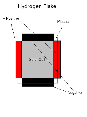
Simple though. Create a roll to roll manufacturing process for 2-10 mm clear plastic solar cells that are slightly denser than water. Dump them in a clear top tank or pool with water and an electrolyte that is  lighter than the solar cells (Hydrogen Flakes), and let the sun produce hydrogen.

Creating hydrogen flakes for various frequencies of light and placing them in the same tank allows you to up the hydrogen output by capturing different frequencies of the available light. The efficiency of the hydrogen flakes doesn’t matter, as the same light will hit many flakes as it travels through the water. Mirroring or silvering the bottom of the tank will also increase the amount of hydrogen produced as the light will be reflected upward and through the Hydrogen Flakes for second pass.

The flakes will float as bubbles of hydrogen and oxygen are formed and stick to the edges of the hydrogen flakes, making them more buoyant. They will rise until the bubble become large enough to detach, they impact another flake, or they come to the surface where the bubbles will burst.  They will then fall to the bottom of the tank to begin their journey again.

The ones that work will float to the top, the ones that are non functional will stay on the bottom, this allows for a simple self sorting method for removal of non functional hydrogen flakes.

This system will also produce low grade waste heat, as electrolysis is inherently inefficient. The waste heat can be converted into electricity using an LTD Stirling. Using a pool or tank with a black bottom, instead of a mirrored or silvered one, will increase the thermal absorption. With the waste heat the hydrogen flakes will produce a silver bottom is probably the better option.

It really can’t be that simple to solve the world energy problems, can it?

<- Previous      Next ->                               Contact

Posted in Uncategorized | 3 Comments

Image Of The Final Design

<- Previous     Next ->                               Contact

Posted in Uncategorized | 40 Comments

The Evolution Of The Final Design

The Evolution Of The Final Design (aka inventing an age of abundant energy for the future)

For years the production of energy has fascinated me. Over the past 20 years I have experimented with solar cells made via inkjet printer, a hydraulically coupled compressor and turbine based on Tesla’s turbine, vertical wind turbines, high temperature cracking of water, high COP heat pumps, all the different varieties of Stirling engines, and many other energy projects. Continuously going back to old projects to incrementally improve them and make them perfect has been fun, except perfect is the enemy of finished, hurricane Sandy has made me realize that we need simple, scalable, cheap, and locally produced power.

4 Inch Diameter LTD Stirling

The re-design of the LTD Stirling began five years ago, a week after placing this Stirling on my cable box. The unit has been running almost continuously for five years with no maintenance. It has been a constant reminder high tech isn’t always the solution. Sometimes looking at old technology from a different perspective can solve problems in a simpler and more cost effective way.


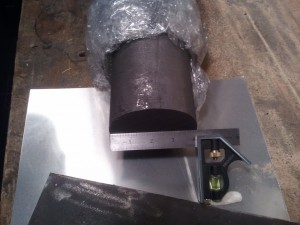
4 Inch Graphite Piston Material

Version 1 was nothing more than scaling up the design from a 4 inch diameter LTD unit to a 2 by 2 foot, 4 square foot device. This was to test the energy output of a scaled up unit. It ran from 0 to ~70 watts depending on the temperature differential between the hot and cold side and the stroke length. It had a 4 inch diameter graphite piston and a cast aluminum cylinder 10 inch long by 5 inch OD with a ~4 inch ID. The piston strokes length could be varied from 1/2 inch to ~5 inches, by adjusting one screw on the fly wheels hub.

Dual Action Stirling Engine

Dual Action Stirling Engine

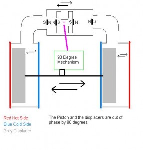
Version 2 removed the flywheel and replaced it with two sets of rare earth magnets to “spring load” the piston at the end of each stroke, effectively storing the pistons momentum.  Two sets of hot and cold plates where employed using a shared piston. When one side was in the contraction phase the other was in expansion phase and vice versa.

Versions 3 to 6 were variations on the same dual action theme. The highest cycle rate and power output was the final design with in excess of 2,000 C.P.M. and a 250 watt power output. The entire unit was about the size of a 5 gallon bucket.

emachineshop.com rotary Stirling

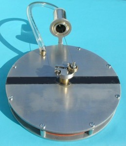
Version 7 was the first rotary Stirling built in my shop. It was a modified clone of a device found at emachineshop.com. The black line in the image separates the hot and cold sides of the device. The advantage of this device is its minimal number of friction points, 3 bearings and one piston. It is scalable, by adding one bearing you can stack many of these all linked together by the same shaft, while only needing to increasing the diameter or stroke length of the piston.

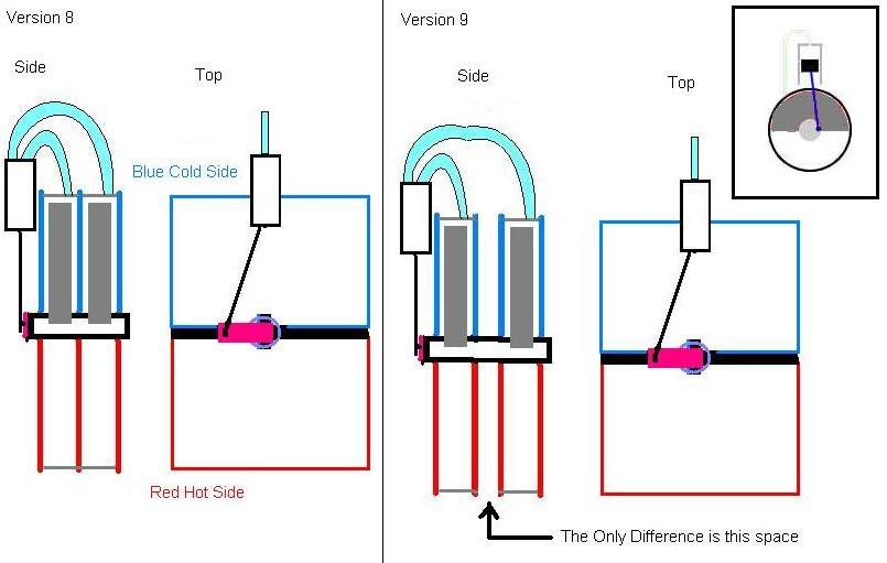
Versions 8 and 9 were variations on the rotary Stirling, they are stacked rotary Stirling engines. The displacers are D shaped half circles. The only difference between V 8 and V 9 is the space allowing for greater heat transfer.

Versions 8 and 9 and D shaped displacer

Version 10 is the final version. It was designed over the period of a week while the power was out from hurricane Sandy. It takes into account all the design revisions from all previous devices. It is designed to be manufactured at high speed using plastic injection molding technology that has been around for over 50 years. A 4 kilowatt unit will cost between $180-$350 and have a life span of 25-35 years. The only wear it will have is three bearings that cost $2 each, and are easily replaceable. They will be voluminous devices, but extremely light weight, weighing in at around 55 to 70 pounds. The size will be 3 by ~3 by ~6 feet. They are designed to be both ground mounted vertically and rack mounted horizontally.

The version 10 design is simplicity itself. 

<- Previous     Next ->                               Contact


Posted in Energy | 2 Comments